
Taking FreeRTOS for a spin on an Arduino
As I mentioned on my previous post, I got an Arduino kit to start experimenting with the platform and eventually interconnect it with the Snap Circuits so that my grandkids and I can have fun building some cool projects. The kit includes an Arduino Mega2560 board and a bunch of components that can be used to build a variety of projects.
It is pretty easy to get started with the Arduino platform. You install the Arduino IDE, plug in the board to your computer using the USB cable, and boom! you are up and running in minutes. I am using the new version 2 of the IDE, and so far it has been very stable.
Multitasking
To warm up, I decided to do a silly project that combines several capabilities all at once. Even though the Arduino platform is very easy to use, if you need to do multiple things at the same time, it can get out of hand very quickly trying to keep track of the required timings and switching between functions. A giant loop() function with a bunch of delay() calls will definitely not cut it, except for really small projects. You really need to have a good methodology to keep the various functionalities nicely organized, making sure the processor is fairly shared across functions, and minimizing side effects between them.
I looked at a couple of frameworks to try out: TaskScheduler, loopTimer, ArduinoThread, AceRoutine, and FreeRTOS. I chose to take FreeRTOS for a spin to get started.
FreeRTOS
“FreeRTOS is a real-time kernel (or real-time scheduler) on top of which embedded applications can be built to meet their hard real-time requirements. It allows applications to be organized as a collection of independent threads of execution,” quoted from “Mastering the FreeRTOS Real Time Kernel” by Richard Barry, the original developer.
But, oops! the first thing I noticed was that FreeRTOS is a pure C framework, whereas the Arduino platform is all C++. Of course the two can play together, but without the object orientation of C++, mixing C and C++ is going to start to look pretty ugly in no time. A way to handle this is to create C++ wrappers for FreeRTOS. But that is a little bit of a pain and not a great way to get my project started. But, hey! it did not take a lot of googling to find someone who actually developed and published the wrappers: “frt - Flössie’s ready (FreeRTOS) threading”, a header file with a pretty good set of class declarations on top of FreeRTOS. Woo hoo! What a relief!
There are a lot of tutorials out there that introduce FreeRTOS concepts. Here is one, for example. One caveat is that none of the tutorials available show how to use FreeRTOS with the frt wrappers. However, it is super straightforward to use and there are some really good examples in the project repo.
Project functionality
The project does the following:
-
We start with the platform in power savings mode
-
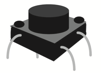
Pressing a push button
- Wakes up from power saving mode
- Emits a buzzing sound
- Starts blinking an LED
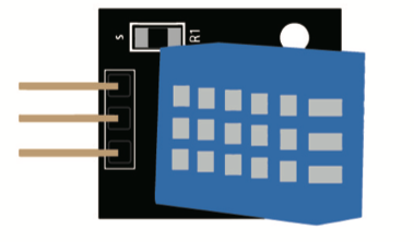
- Measures temperature and humidity every 4 seconds
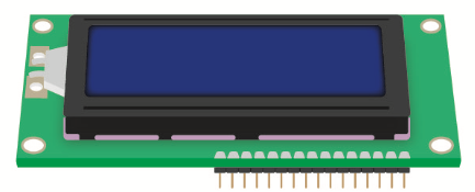
- Displays the data on a 16x2 LCD screen.
-
Pressing the button again
- Sounds the buzzer with a different tone
- Stops blinking the LED
- Stops measuring temperature and humidity
- Turns off the LCD screen
- Goes back to power savings mode.
-
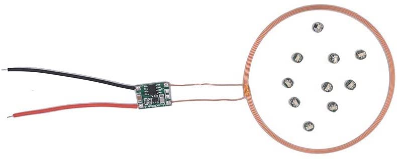
Regardless in what mode the platform is, detecting a loud sound turns on an induction coil that powers a bunch of wireless LEDs. And, if the platform is awake, also move a servo motor to put some of the LEDs above the coil so that they are turned on.
-
Clapping again turns off the induction coil (and the wireless LEDs). If the platform is awake, the servo moves the LEDs away from the coil, thus turning them off.
Hardware components
Here is the list of components used in this project.
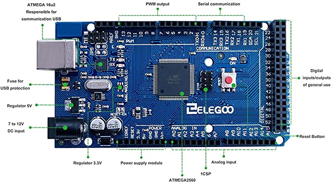
Arduino Mega2560 Board


Discrete components
Circuit layout
The diagram below lays out the hardware component connections for the project.

Circuit schematic
The table below lists each Arduino Mega2560 Board pin, which components are attached, the type of interface, and a brief discussion of each item.
| Arduino Pin | Component | Type | Description/Notes |
|---|---|---|---|
| PWM 2 | Push button | Input | The push button Pin is configured as INPUT_PULLUP, thus saving us a resistor. When pushed, an interrupt is generated on LOW. |
| PWM 3 | LCD display contrast control. | Pulse Width Modulation (PWM) wave output | LCD off: 0% duty cycle. LCD on: 80% duty cycle. To eliminate a buzzing sound, we include a low pass filter (1KΩ, 100μF). |
| PWM 4 | Induction LEDs | Digital output | Since the induction LED coil draws over 80mA of current, which is too much for an Arduino output pin, we need to use a transistor switch. |
| PWM 5 | Temperature & humidity sensor | Digital output/input | Access to the sensor is handled by the DHTNew library. This library appears to behave well under FreeRTOS. |
| PWM 6 | LCD Display Register Select (RS) | Digital output | Access to the LCD display is handled by the standard Arduino LiquidCrystal library. This library appears to behave well under FreeRTOS. |
| PWM 7 | LCD Display Enable (EN) | Digital output | Same as above. |
| PWM 8 | Active Buzzer | PWM output | Access to the active buzzer is handled by the standard Arduino tone() library. This library appears to behave well under FreeRTOS. However, I am only generating two short tones. I have not tested longer music-like tone sequences. |
| PWM 9, 10, 11, 12 | LCD Display data pins 7, 6, 5, 4 | Digital output | Same as PWM 6 & 7. |
| PWM 13 | LED light | Digital output | HIGH turns on the LED, LOW turns off the LED. Pin 13 is also connected to the internal Mega2560 LED. |
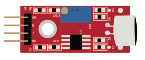
| RX 19 | Sound Sensor Digital Output (DO) | Digital input | When sound is detected, the DO pin is raised and an interrupt is generated on HIGH. |
| PM 45 | Servo Motor Pulse Input | PWM output | A pulse of 0.5-2.5ms duty cycle over a period of 20ms will move the servo to 0 to 180°. |
Software layout
The diagram below depicts how the project is divided in FreeRTOS tasks, shown in blue. It also shows inter-task communication via semaphores and a queue, shown in yellow. And in addition, it shows the interrupt service routines need to handle some external events (e.g., button press), shown in orange. Finally, the isAwake global flag is shown in green.
All the code used on this project is available here.

Tasks diagram
Below we describe each one of the software components depicted above.
| Component | Type | Description |
|---|---|---|
| Init | Arduino setup() function | Starts FreeRTOS tasks and enables interrupts. |
| Button ISR | Interrupt service routine | Handles push button interrupts. Posts to button_semaphore. |
| Sound ISR | Interrupt service routine | Handles “clapping” sound interrupts. Posts to clap_semaphore. |
| Timer0 Compare ISR | Interrupt service routine | Handles timer interrupts. It is invoked every millisecond. Provides timing for the SoftServo component (20ms period). |
| button_semaphore | FreeRTOS Semaphore | A button-press interrupt posts to this semaphore. The Button Task waits on it. |
| wakeup_semaphore | FreeRTOS Semaphore | The Button Task post to this semaphore. The Blink Task waits on it. |
| clap_semaphore | FreeRTOS Semaphore | A sound interrupt is used to post to this semaphore. The Clap Task waits on it. |
| servo_semaphore | FreeRTOS Semaphore | The Clap Task posts to this semaphore. The Servo Task waits on it. |
| LCDQueue | FreeRTOS Queue | The Measure Task writes data to this queue, which is read by the DisplayLCD Task. |
| isAwake | Volatile Global | This flag is only toggled by the Button Task. Some of the other tasks just read its value. |
| Button Task | FreeRTOS Task | Waits for button_semaphore, toggles isAwake, beeps the buzzer, and posts to wakeup_semaphore. While buzzing, we need to disable the sound interrupt to prevent the buzzer from triggering the sound sensor. Note that since this is the only task that updates the isAwake flag, I determined that it was not necessary to protect it with a mutex.Also note that this is the highest priority task, it is very short lived and we need to make sure it is always responsive. |
| Blink Task | FreeRTOS Task | This task blinks a LED if isAwake is true. |
| Measure Task | FreeRTOS Task | This task measures temperature and humidity if isAwake is true. When data is available, it pushes it to the LCDQueue. |
| DisplayLCD Task | FreeRTOS Task | Reads the LCDQueue and displays the data on an LCD screen. |
| Clap Task | FreeRTOS Task | Waits for the clap_semaphore, toggles the induction LEDs on/off and posts to the servo_semaphore. |
| Servo Task | FreeRTOS Task | Waits on the servo_semaphore and if isAwake is true, moves the servo closer to the induction coil. While operating, it is necessary to disable the sound interrupt to prevent the noise of the moving servo from triggering the sound sensor. |
| SoftServo | Instance of Adafruit_SoftServo | This object is used to control the servo. Generates 0.5-2.5 ms duty cycle pulses, depending on desired servo positioning (0-180°). I had trouble finding a servo library that would work with FreeRTOS. Apparently, the standard libraries have some timer/timing conflicts with FreeRTOS. Fortunately, I found Adafruit_SoftServo, an extremely simple library that only requires a 20ms refresh generated by tapping the Arduino Timer0 1ms interrupt. |
| Idle Task | FreeRTOS Task, Arduino loop() function | The idle task is used to enter power savings mode when isAwake is false. |
And here are some pictures of the project implementation.
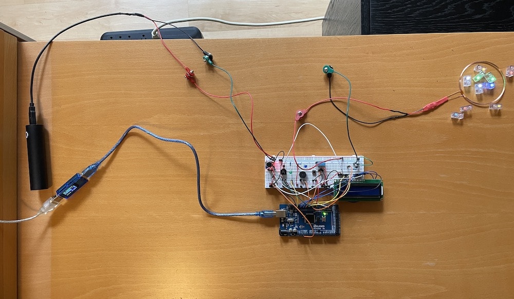
Full view of the project (without servo)
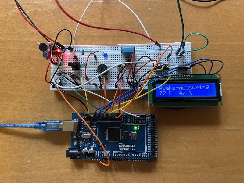
Close up
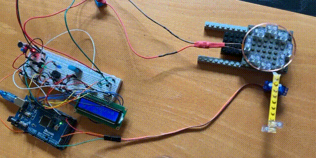
Adding the servo
Power consumption
Below are the power consumption measurements I took under the various scenarios.
| Mode | Power consumption |
|---|---|
| Low power | 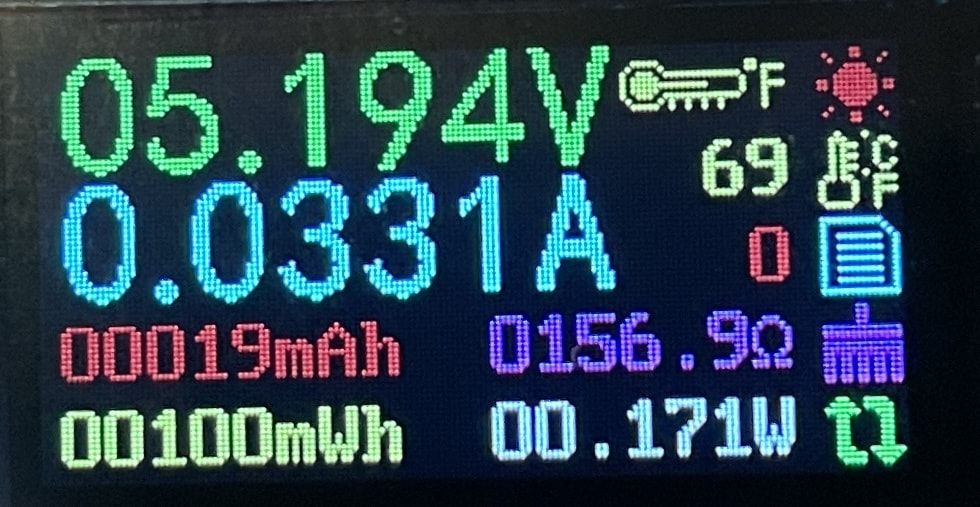 |
| Awake | 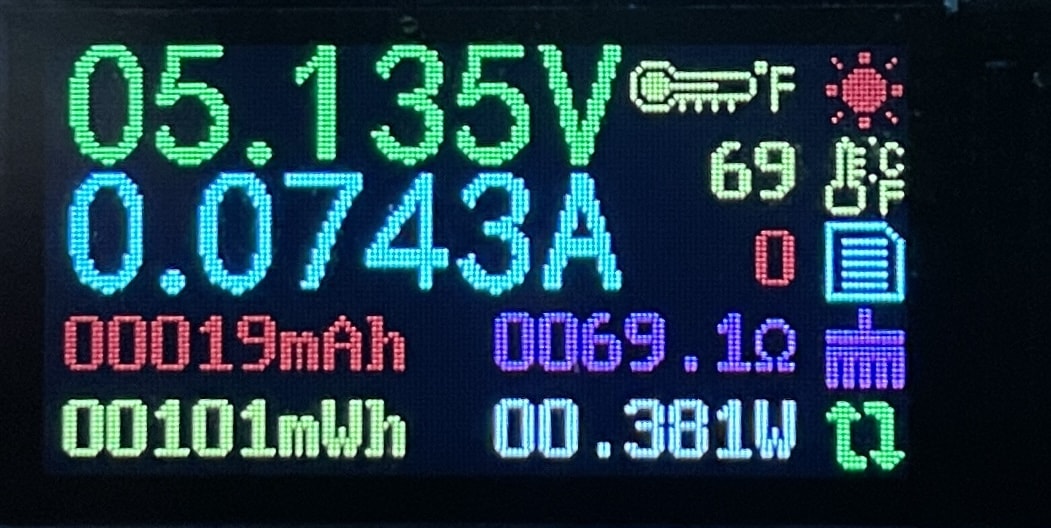 |
| Induction leds on | 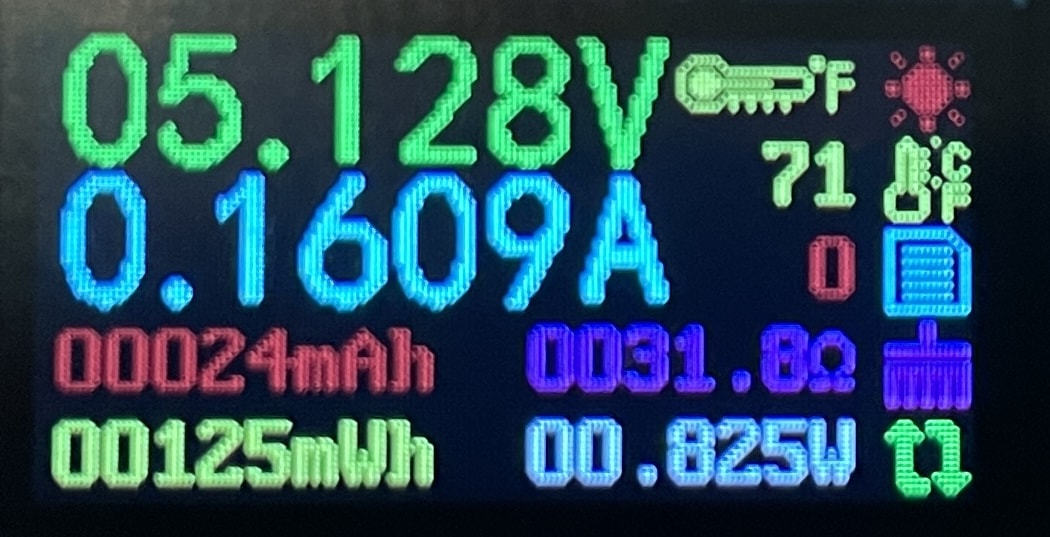 |
| Induction leds on and servo active | 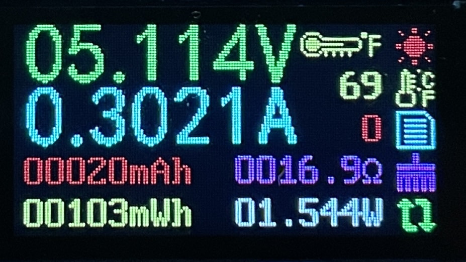 |
The low power mode is not particularly impressive. I don’t know if FreeRTOS is not letting the platform enter power saving mode as much as it could.
Concluding remarks
I was very pleased with FreeRTOS and the functionality it provides. It is great to be able to split up a project into separate parts (tasks) that can be developed almost independently. Communication between tasks can be easily achieved using semaphores, mutexes and/or queues. Perhaps for many situations FreeRTOS may seem overkill, but if the project combines more than a handful of sensors/actuators, with somewhat complex logic, FreeRTOS can help keep things under control.
Nevertheless, there are a couple of drawbacks to consider when using FreeRTOS on the Arduino platform:
-
Due to timing issues or possible conflicts in the use of timers, some standard Arduino libraries may not be compatible with FreeRTOS. For example, the standard Servo library doesn’t work with FreeRTOS. I had to search for an alternative or be ready to write my own interface.
-
The FreeRTOS timer granularity of 15ms (default) may not work for all projects. For example, in the case of the servo interface, we need to be able to generate 0.5ms to 2.5ms pulses every 20ms. I had to use a timer interrupt to refresh the servo interface, which operates completely outside of a FreeRTOS task. Not a huge deal, but something to keep in mind.
My next experiment is to re-implement this project using one of the alternatives I mentioned at the beginning. I am particularly intrigued by the AceRoutine cooperative multitasking framework, which is based on the concept of coroutines. I expect that it would be a lot more compatible with mainstream Arduino libraries, and perhaps a happy medium between bare Arduino and a full blown RTOS.
Until then, auf wiedersehen!
PS: Oh, by the way, do you want to start playing with Arduino, FreeRTOS and other stuff without having to deal with hardware, cables, or installing any software whatsoever? Try Wokwi. It is a full blown simulator of the Arduino platform that runs in your browser!